? Table of Contents
- Introduction and Characteristics of CNC
- Key Elements of CNC
- CNC Process Parameters
- Common CNC Post-Processing
- Basic Structural Design for CNC Products
- Preliminary Assessment of CNC Product Manufacturability
? 1. Introduction and Characteristics of CNC
? 1.1 Definition of CNC
CNC (Computer Numerical Control) is a computer-controlled automation system for machine tools.
A CNC machine is an automated machine tool controlled by a program. Its control system can logically process programs with control codes or other symbolic instruction sets. These instructions are decoded by a computer, causing the machine to perform predetermined actions. Material is removed from a solid block via cutting tools to produce semi-finished or finished parts based on a CAD model.
CNC machining is a subtractive manufacturing technology that uses high-speed rotating cutting tools to remove material from a solid block to produce parts.
? 1.2 Characteristics of CNC Machining
- Parts exhibit high dimensional accuracy and tight tolerances.
- Suitable for both high-volume production and one-off jobs.
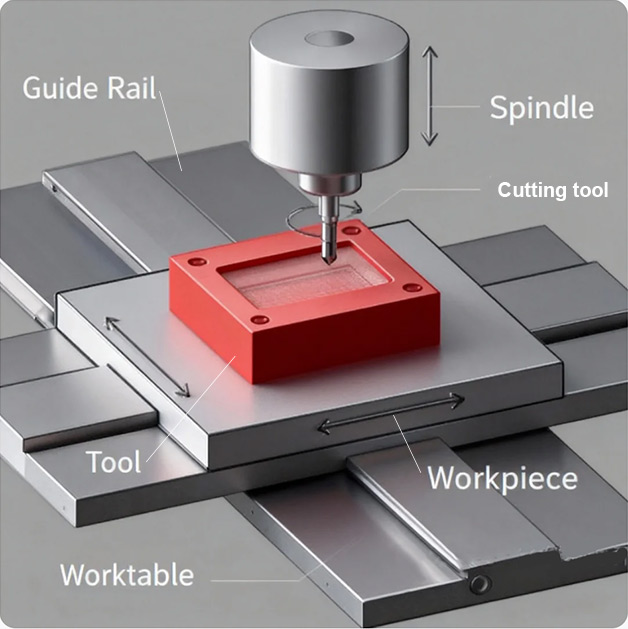
Core Components: Spindle, Guide Rails, Cutting Tool, Workpiece, Worktable
? 2. Key Elements of CNC
? 2.1 Materials
? 2.1.1 Commonly Machined Materials
- Metals: Aluminum, Stainless Steel, Brass, Titaniuml, Copper, Alloy steel
- Plastics: ABS, PC, Nylon, PP, PTFE (Teflon), POM, PMMA, etc.
? 2.1.2 Material Classification (by Source)
| Type | Description | Advantages | Disadvantages |
|---|---|---|---|
| Sheet/Plate | Simple cutting processes. | Relatively stable material properties, favorable for machining. | High material waste, long machining time, not ideal for high-volume production. |
| Profiles | Custom shapes to reduce machining volume or for special structures. | Reduces machining allowance and special structure processing, shortens machining time and raw material cost. | Profile dimensional accuracy is difficult to guarantee, may not meet Class A surface finish requirements. |
| Forged Blanks | Often made from forged plates. | Saves material and time, can create shapes not possible with profiles. | Risk of datum shift between forging and CNC processes; forging stress can reduce machining stability. |
| Stamped Blanks | Simple punching/blanking from sheet/coil material. | Reduces machining allowance and time, provides rough datum for CNC. | Risk of deformation from stamping, posing risks for surface locating during CNC. |
| Die-Cast Blanks | For parts with high-precision features, post-machining on critical holes/surfaces. | Adapts to parts with high feature requirements. | Risk of porosity when machining allowance is large; requires prior customer approval standards. |
? 2.2 Machine Tools
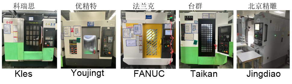
? Mainstream Brands and Parameter Comparison
| Brand | Precision | Advantages | Disadvantages |
|---|---|---|---|
| Taichung/Taikan | <0.004mm | Cost-effective, widely used. | Average performance, slow response. |
| FANUC | <0.004mm | High machining efficiency and precision. | Slightly higher price, closed system. |
| Beijing Jingdiao | 0.0018mm | High precision, excellent surface finish. | Slightly higher price, not suitable for heavy cuts. |
? Key Machine Tool Parameters
- Available Power
- Age/Condition (Stability)
- Horizontal/Vertical Configuration
- Spindle Type and Specifications
- Number/Configuration of Axes
- Workholding Method
? 2.3 Cutting Tools
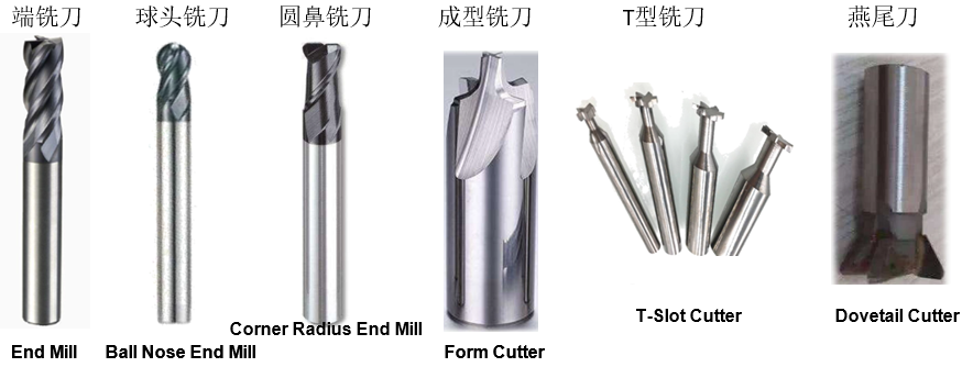
? 2.3.1 Common Milling Cutter Types and Applications
| Tool Type | Application |
|---|---|
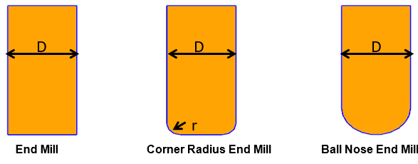
| End Mill / Square End Mill | Cutting edges on side and bottom. Suitable for roughing and finishing sides, bottoms, slots, pockets, planar surfaces. Not ideal for curved surfaces. |
| Ball Nose End Mill | Suitable for complex 3D contours. Not ideal for flat surfaces. |
| Corner Radius End Mill (Bull Nose) | Used for roughing and finishing side/bottom features with radiused corners. |
| Form Cutters (Incl. T-Slot, Dovetail, Chamfer Mills) | Customized for specific features. Used for machining special structures. |
? 2.3.2 Milling Cutter Material Performance Comparison
| Type | Common Grades | Hardness (HRC/HRA) | Bending Strength (GPa) | Hot Hardness (℃) | Machinability/Properties | Applications |
|---|---|---|---|---|---|---|
| High-Speed Steel (HSS) | W9Mo3Cr4V, W6Mo5CrV2 | 63~69 (82~87 HRA) | 3.43~4.41 | 550~600 | Can be shaped by cold/hot working, good regrindability, minimal heat treatment distortion. | Medium-speed tools (drills, mills, gear cutters). |
| Cemented Carbide | YG (K-class), YT (P-class), YW (M-class) | 69~81 (89~93 HRA) | 1.08~2.16 | 800~1100 | Powder metallurgy formed, grindable only, no heat treatment, relatively brittle. | High-speed cutting tools (turning, planing, milling inserts). |
| Ceramic | SG4, AT6 | 93~94 HRA (1500~2100 HV) | 0.4~1.115 | 1200 | Pressed and sintered, grindable only, brittleness slightly higher than carbide. | Turning tools, suitable for finishing continuous cuts. |
| Cubic Boron Nitride (CBN) | FD, LBN-Y | 7300~7400 HV | 0.57~0.81 | 1200~1500 | High-temperature/pressure sintering, hardness higher than ceramic, very brittle, grindable with diamond wheel, no heat treatment needed. | Machining high-hardness, high-strength materials (especially ferrous). |
| Polycrystalline Diamond (PCD) | - | ~10000 HV | 0.42~1.0 | 700~800 | Highest hardness, extremely brittle. | High-precision, low-Ra machining of non-ferrous metals; precision machining of non-metals (not for ferrous metals). |
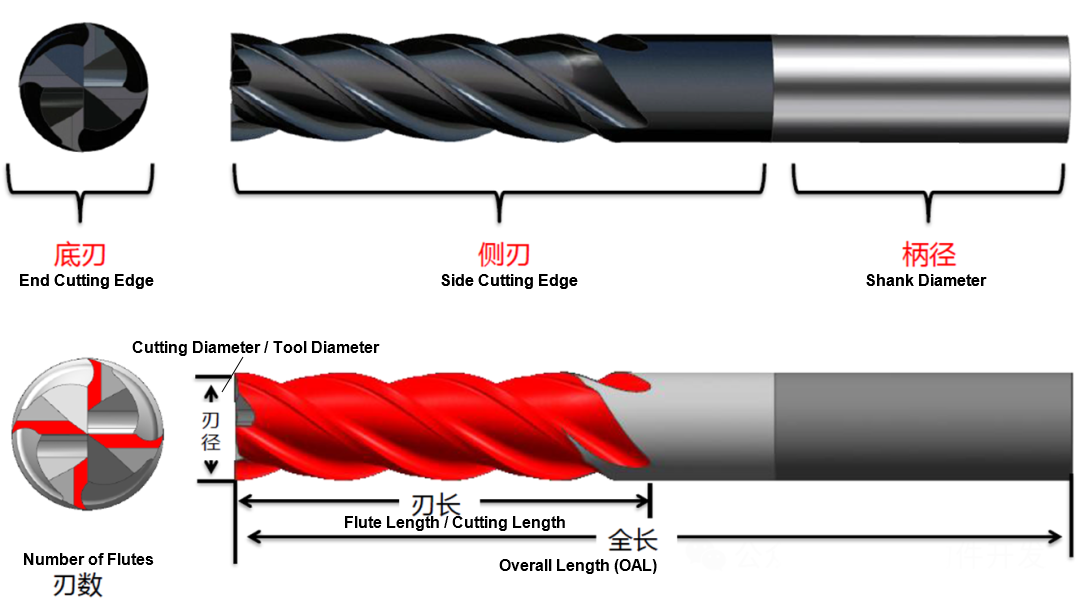
Core Parameters: End Cutting Edge, Flute Length, Number of Flutes, Side Cutting Edge, Shank Diameter, Overall Length.
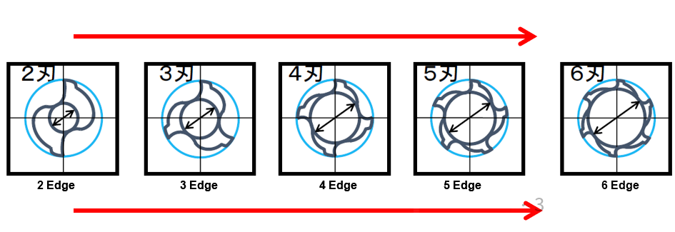
- From left to right, more flutes → smaller chip gullet → poorer chip evacuation.
- From left to right, more flutes → better rigidity → less prone to breakage, less deflection.
? 2.3.4 Tool Holding
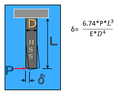
- Relationship between tool overhang (holder length) and deflection:
- Key Conclusion: If overhang (L) doubles, deflection increases 8-fold. If tool diameter (D) doubles, deflection reduces to 1/16.
- Optimization Suggestion: Where possible, use the shortest overhang and largest tool diameter to improve machining efficiency and quality.
? 2.3.5 Milling Cutter Selection Guidelines
- Common Diameters
- Common End Mill/Ball Nose Diameters:
- Hard Materials (Steel): D1, D1.5, D2, D2.5, D3, D3.5, D4, D6, D8, D10, etc.
- Soft Materials (Aluminum, Copper): D1, D2, D3, D4, D6, D8, D10, etc.
- Common Corner Radius End Mill Diameters: D2r0.5, D3r0.5, D3r0.2, D4r0.5, D4r1, D6r1, D8r1, D10r3, etc.
- Common End Mill/Ball Nose Diameters:
- Selection Principle:
- "Big Tool" Principle: Larger tools remove more material per pass, reducing machining time and cost.
- Example: For an R2.1 internal corner, available tools are D4, D3, D2, D1. Prioritize D4 for highest efficiency and minimal deflection.
- T-Slot / Dovetail Cutter Usage:
When certain part surfaces cannot be accessed directly from above and standard tools cannot machine them, T-slot or dovetail cutters are used for undercuts.
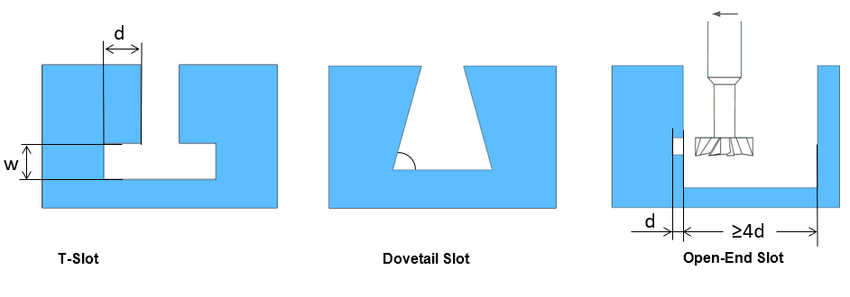
- T-Slot Cutter: Undercut width
wshould be ≥ 3mm and an integer value. - Dovetail Cutter: Common angles 45°/60° (customizable). Cutting diameter to shank diameter ratio commonly 2:1. Reserve ≥ 4d space for single-side undercut.
- T-Slot Cutter: Undercut width
? 2.4 Fixtures
? 2.4.1 Functions of a Fixture
- Locating: Positions the workpiece relative to the machine tool and cutting tool.
- Clamping: Secures the located workpiece to prevent movement during machining.
? 2.4.2 Locating Principle (Six-Point Locating Principle)
A workpiece has six degrees of freedom in a 3D Cartesian coordinate system. A fixture uses six reasonably distributed support points to restrict these six degrees, fully determining the workpiece's position.
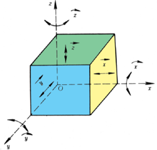
- Complete Location: All six degrees are restricted.
- Incomplete Location: Only necessary degrees are restricted (acceptable if machining requirements are met).
- Over-Location: A degree is redundantly restricted (avoid).
- Under-Location: A required degree is not restricted (not allowed).
? 2.4.3 Clamping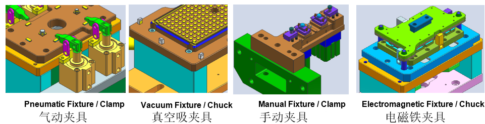 Method Comparison
To maintain the located position under cutting forces, inertia, gravity, etc., a fixture needs a clamping mechanism to apply appropriate clamping force.
| Type | Advantages | Disadvantages |
|---|---|---|
| Pneumatic Clamping | Low cost, high efficiency, widely used. | Unstable air pressure can cause insufficient clamping, risk of part damage. |
| Vacuum Clamping | No part damage from clamping force. | Relatively weak clamping force. |
| Manual Clamping | Low cost. | Complex operation, imprecise torque control, risk of part damage. |
| Electromagnetic Clamping | High clamping force. | Heating during operation can weaken magnetism, risk of insufficient clamping, high cost, risk of part damage. |
? 3. CNC Process Parameters
In milling, the relative motion between the cutter and workpiece is the cutting motion. The cutter's rotation is the primary motion; its linear/rotary feed relative to the workpiece is the feed motion.
? 3.1 Core Parameter Definitions
| Parameter | Definition | Formula |
|---|---|---|
| Cutting Speed (Vc) | Speed of primary motion, linear speed at cutter periphery (m/min). | (d = Tool Diameter [mm], n = Spindle Speed [rpm]) |
| Feed Rate | Feed per Tooth (fz): Workpiece movement per cutter tooth (mm/z). Feed per Revolution (fr): Workpiece movement per cutter revolution (mm/r). Feed per Minute (fm): Workpiece movement per minute (mm/min). |
(z = Number of Flutes, mm/r) (mm/min) |
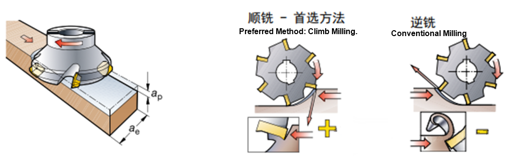
| Radial Depth of Cut (a_e) | Width of material engaged radially by the cutter (mm). (Distance across the machined surface.) | - |
| Axial Depth of Cut (a_p) | Depth the tool penetrates below the uncut surface (mm). (Distance tool plunges into material.) | - |
? 3.2 Climb Milling vs. Conventional Milling
| Type | Definition | Advantages |
|---|---|---|
| Climb Milling (Down Milling) | Cutter rotation direction matches workpiece feed direction at the point of cut. Chip thickness starts at maximum and decreases. | Avoids burnishing effect, less heat generation, reduces work hardening. Chip starts thick, reducing initial tool wear, leading to higher tool life. |
| Conventional Milling (Up Milling) | Cutter rotation direction opposes workpiece feed direction at the point of cut. Chip thickness starts at zero and increases. | Chip starts thin, tool rubs before engaging, causing faster wear and increased work hardening. |
- Preferred Method: Climb Milling.
? 4. Common CNC Post-Processing
? 4.1 Cleaning
Removing oil/grease from CNC machined part surfaces.
- Purpose: Prevent corrosion and contamination.
- Method: Detergent + automated washing + drying.

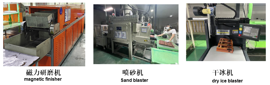
? 4.2 Deburring (Metal or Plastic)
Removing burrs left after CNC machining.
- Methods: Magnetic tumbling, vibratory tumbling, sand blasting, dry ice blasting.
- Equipment: Sand blaster, dry ice blaster, magnetic finisher.
? 5. Basic Structural Design for CNC Products
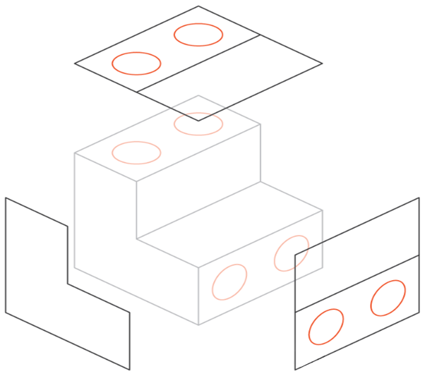
? 5.1 Minimize Number of Setups
- Multiple setups require re-establishing datums, introducing errors: The toolpath is a primary constraint in milling. To access all surfaces, the part must be rotated/flipped multiple times. Each rotation requires re-establishing machine datum and a new coordinate system (especially for 3-axis machining).
- Machine related features in the same setup for positional accuracy: For maximum positional accuracy between two or more features, machine them in the same setup. New setups introduce small but non-negligible errors regardless of fixture precision. More setups inevitably reduce accuracy.
? 5.2 Avoid Deep Slots/Holes/Pockets
- Deep features require long tools, prone to breakage, vibration, and poor chip evacuation.
Deep, narrow slots require long tools which are prone to breakage and can cause tool/chatter vibration. Machining a deep slot requires multiple passes, increasing time and cost.
Milling deep pockets leads to tool overhang, deflection, chip evacuation issues, and tool breakage. Generally limit pocket depth to 4-5 times its length (max dimension in XY plane) for optimal cost.
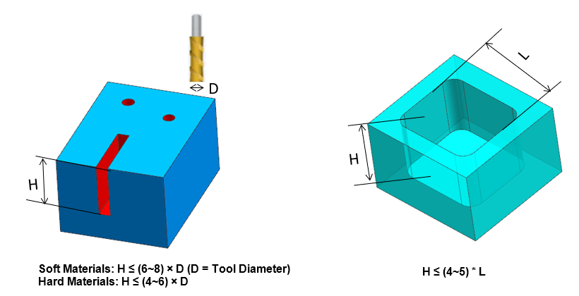
- Depth Limit Guidelines:
- Pocket Depth ≤ 4~5 × (Max XY Plane Dimension) →
H ≤ (4~5) * L - Soft Materials:
H ≤ (6~8) × D(D = Tool Diameter) - Hard Materials:
H ≤ (4~6) × D
- Pocket Depth ≤ 4~5 × (Max XY Plane Dimension) →
? 5.3 Edge Treatment
- Internal sharp corners cannot be machined; design internal radii (recommended ≥1.0mm, min R0.5mm).
Since all milling tools have a circular rotating profile, they cannot create internal sharp corners or chamfers. The tool leaves an unmachined radius equal to its own radius. While EDM can machine sharp internal corners, it's expensive. To leverage larger tools, design the largest possible internal radius, preferably >1.0mm, minimum R0.5mm.
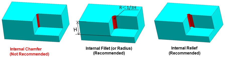
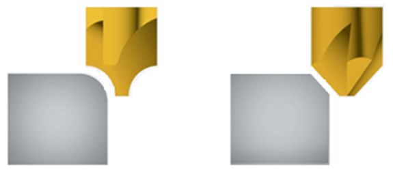
- Chamfer (rather than fillet) the top edges of features.
Fillets on the top edges of bosses or slots require custom form tools, increasing cost. It's recommended to use chamfers instead of fillets on these edges, unless necessary.
? 5.4 Wall Thickness Design
Thin walls in metal increase chatter, affecting accuracy and surface finish. In plastics, they cause warping and softening.
| Material | Recommended Wall Thickness | Minimum Wall Thickness |
|---|---|---|
| Metal | ≥ 0.8mm | 0.5mm |
| Plastic | ≥ 1.5mm | 1.0mm |
 [img]
[img]
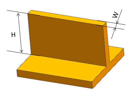
- Tall, Thin Features: For reduced vibration, aim for
Height < 4 × Width (H < 4W).
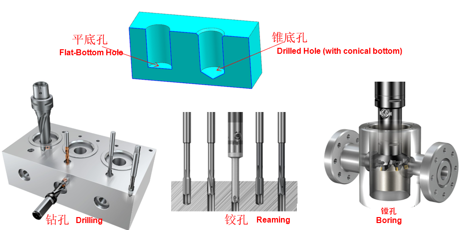
? 5.5 Hole Machining
Standard diameter holes can be drilled.
- Standard Holes (Drilled):
- Max depth recommended: 4 × nominal diameter. Typical: 10×. Feasible: up to 40×.
- Reamers/Bores are used for finishing holes with tight tolerance requirements. Standard diameters are recommended.
- Non-Standard Holes: Machined with an end mill (observe max depth limits).
- Blind Holes: Drilled holes have conical bottoms; end milled holes have flat bottoms.
? 5.6 Threaded Hole Machining
- Methods: Tapping (M2 and above), Thread Milling (min. ~M6).
- Avoid deep tapping for accuracy: longer tap depth increases risk of vibration/deflection, causing defects.
- A thread engagement length of 1.5 × diameter provides sufficient strength, as most load is borne by the first few threads. Do not exceed 3 × tap diameter for thread length.
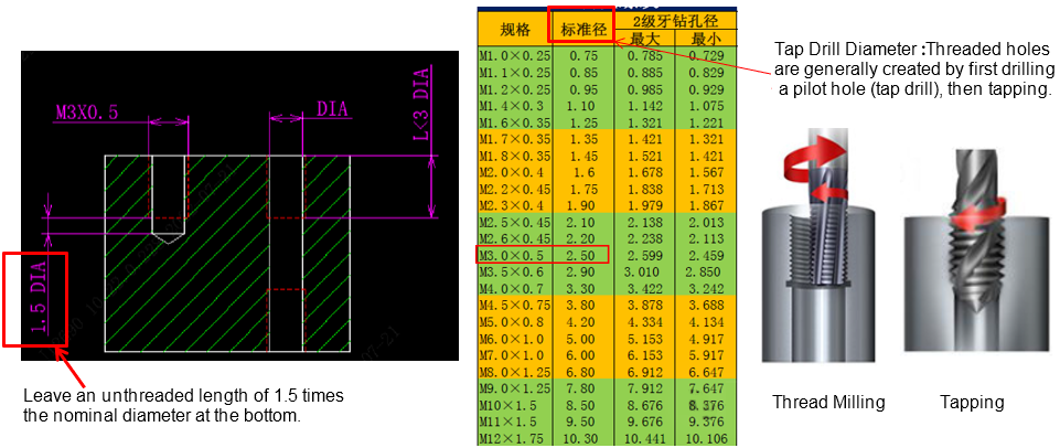
? Thread Pre-Drill Diameter Reference Table
| Thread Size | Tap Drill (Standard) | Class 2B Tap Drill (Max) | Class 2B Tap Drill (Min) |
|---|---|---|---|
| M1.0×0.25 | 0.75 | 0.785 | 0.729 |
| M1.1×0.25 | 0.85 | 0.885 | 0.829 |
| M1.2×0.25 | 0.95 | 0.985 | 0.929 |
| M1.4×0.3 | 1.10 | 1.142 | 1.075 |
| M1.6×0.35 | 1.25 | 1.321 | 1.221 |
| M1.7×0.35 | 1.35 | 1.421 | 1.321 |
| M1.8×0.35 | 1.45 | 1.521 | 1.421 |
| M2.0×0.4 | 1.6 | 1.678 | 1.567 |
| M2.2×0.45 | 1.75 | 1.838 | 1.713 |
| M2.3×0.4 | 1.90 | 1.979 | 1.867 |
| M2.5×0.45 | 2.10 | 2.138 | 2.013 |
| M2.6×0.45 | 2.20 | 2.238 | 2.113 |
| M3.0×0.5 | 2.50 | 2.599 | 2.459 |
| M3.5×0.6 | 2.90 | 3.010 | 2.850 |
| M4.0×0.7 | 3.30 | 3.422 | 3.242 |
| M4.5×0.75 | 3.80 | 3.878 | 3.688 |
| M5.0×0.8 | 4.20 | 4.334 | 4.134 |
| M6.0×1.0 | 5.00 | 5.153 | 4.917 |
| M7.0×1.0 | 6.00 | 6.153 | 5.917 |
| M8.0×1.25 | 6.80 | 6.912 | 6.647 |
| M9.0×1.25 | 7.80 | 7.912 | 7.647 |
| M10×1.5 | 8.50 | 8.676 | 8.376 |
| M11×1.5 | 9.50 | 9.676 | 9.376 |
| M12×1.75 | 10.30 | 10.441 | 10.106 |
? 6. Preliminary Assessment of CNC Product Manufacturability
? 6.1 Overall Assessment Dimensions
- Type of raw material.
- Need for surface treatment (sandblasting, anodizing, painting, plating, etc.).
- Whether part geometry allows for proper fixturing and easy datum location.
- Whether the 2D drawing specifies surface roughness, threaded holes, and geometric tolerances (additional requirements not shown in 3D model).
? 6.2 Common Structure Rationality Analysis
- Deep Slots/Holes/Pockets? Assess against max depth limit guidelines.
- Sharp Internal Corners? Internal sharp corners cannot be machined; add radii. External sharp corners can chip or pose safety risks; prefer chamfers (C-corner) over fillets (ensure uniform chamfer angle; external fillets may require form tools).
- Are Radii Too Small? Small radii require smaller tools, which are weaker, prone to breakage, and reduce efficiency.
- Thin-Walled Structures? Check against minimum wall thickness.
- Are Features Too Close Together? Narrow areas are hard to machine, tools have difficulty accessing, long/small tools break or chatter easily.
- Does the First Setup Need to Leave Process Tabs/Lugs for Subsequent Setups? (For locating in later setups; or to add rigidity, reducing distortion). Or to provide hanging points for anodizing/plating.