This article summarizes 27 common defects in injection molding production, covering their definitions, causes, and targeted solutions. The content is precise and practical, suitable for direct reference in production debugging.
| Defect Category | Defect Name |
|---|---|
| Filling/Molding Defects | Short Shot, Jetting Marks, Sink Marks (Dents), Flow Marks |
| Appearance/Surface Defects | Flash (Burrs), Black Specks, Delamination, Burn Marks, Silver Streaks (Splay), Weld Lines, Haze (Cloudiness), Ejector Pin Marks, Wrinkles (Orange Peel), Gloss Differences (Matt & Glossy Surfaces) |
| Structural Deformation Defects | Warpage, Deformation During Ejection |
| Material/Performance Defects | Bubbles, Cracking, Residual Internal Stress, Glass Fiber Blooming (Fiber Readout), Embrittlement, Stress Marks, Hesitation (Flow Hesitation) |
| Color/Texture Defects | Color Variation, Color Instability, Color Mixing (Streaking) |
| Dimension/Wall Thickness Defects | Wall Thickness Issues |
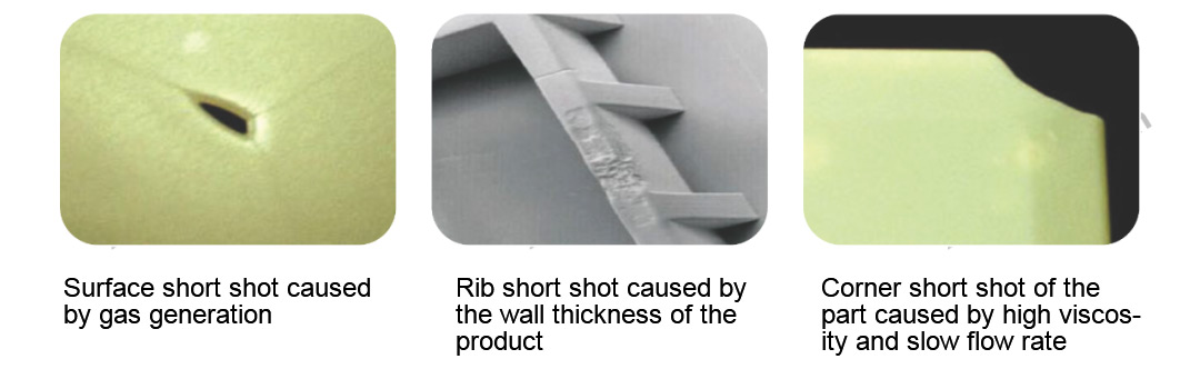
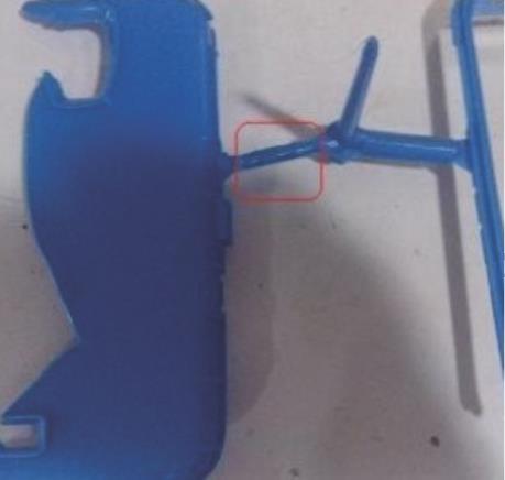
? 1. Short Shot
? Definition
Incomplete filling at the end of the melt flow, or partial cavity underfilling in multi-cavity molds. Often occurs in thin-wall areas or at the end of flow paths. Also known as underfill or short molding.
? Causes
- Excessive flow resistance prevents melt from continuing to flow.
- Factors affecting melt flow length include: part wall thickness, mold temperature, injection pressure, melt temperature, and material composition.
? Short Shot Analysis and Troubleshooting
| Defect Analysis | Corrective Actions |
|---|---|
| Improper control of process conditions. | Adjust accordingly. |
| Injection capacity of the machine is less than the part weight. | Switch to a larger injection molding machine. |
| Runner and gate cross-sections are too small. | Increase appropriately. |
| Melt flow distance within the cavity is too long or there are thin-wall sections. | Add cold slug wells. |
| Poor mold venting; trapped air in the cavity causes short shots. | Improve the mold venting system. |
| Poor flowability of the raw material. | Switch to a resin with better flowability. |
| Low barrel temperature, insufficient injection pressure, or too short pack/hold time can also cause short shots. | Increase the relevant process parameters accordingly. |
? 2. Flash (Burrs)
? Definition
Occurs at mold parting lines, sometimes also at ejector pins and insert positions. Also known as burrs, spew, or fins. Examples: mold parting surfaces, sliding block interfaces, insert gaps, ejector pin clearances.
? Causes
- Insufficient clamping force.
- Melt temperature too high.
- Mold defects leading to poor mold closure.
- Improper control of process conditions; injection speed/pressure too high.
- Abnormal plastic viscosity; uneven raw material granules or insufficient drying.
.jpg)
? Flash (Burr) Solutions
| Category | Solutions |
|---|---|
| Mold Design | - Design mold rationally for tight closure without gaps. - Ensure mold is firmly secured to the platen to prevent damage during molding. - Check vent sizes; they should not exceed the material's flash limit. - Clean mold surfaces; polish surfaces causing poor mold closure for a better seal. |
| Injection Machine | - Set appropriate clamp force. If machine clamp force is insufficient, use a machine with higher clamp force. - Ensure the two mounting platens of the machine are parallel. |
| Molding Process | - Reduce injection speed; reduce injection and holding pressure. - Reduce barrel and nozzle temperature; reduce mold temperature. - Reduce cushion length to prevent over-packing in the barrel. - Increase material cooling rate. |
| Material | - Flash can occur if plastic viscosity is too high OR too low. - Uneven raw material granules cause unstable shot volume, leading to flash. - Materials that absorb moisture strongly or are moisture-sensitive will have significantly reduced flowability if not dried sufficiently. |
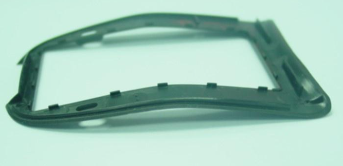
? 3. Warpage
? Specific Causes and Prevention Methods
| Specific Cause/Method | Preventive/Corrective Actions |
|---|---|
| Insufficient/Non-uniform Cooling | Allow sufficient cooling within the cavity; eject only after complete hardening. Alternatively, reduce mold temperature, extend cooling time. |
| Caused by Ejector Pins | Polish the core to reduce ejection resistance, or increase draft angles, add ejector pins in hard-to-eject areas, or change ejection method. |
| Caused by Molding Strain | Increase mold temperature, increase melt temperature, reduce injection pressure, improve flow conditions in the gating system can all reduce the difference in shrinkage in different directions. Most importantly, ensure uniform part wall thickness. |
| Crystalline Plastics | Correction method: create a temperature difference between the moving and fixed halves. Applying a temperature that induces strain on the opposite side of the warp can correct the distortion. Sometimes this temperature difference needs to exceed 20°C but must be very uniformly distributed. |
| Methods to Correct Part Warpage | Place the part to be corrected on a jig, apply weight on the warped area, but the weight and its position must be carefully determined. |
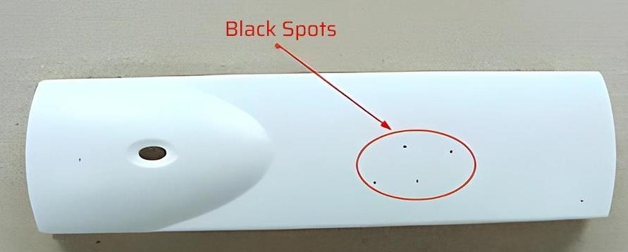
? 4. Black Specks
? Definition
Black specks/contaminants are a major cause of scrap during normal production, primarily affecting appearance. Most contaminants and black specks are foreign substances unrelated to the raw material itself, though a small portion are caused by the material.
? Causes
? Before Molding
- Contamination during raw material processing introducing black specks.
- Impurities during pelletizing causing black specks.
- Raw material contaminated with color masterbatch or flake/regrind with specks.
- Material impurity; high-melt pellets mixed into low-melt material.
- Contamination during packaging, transportation, storage.
- Raw material contamination during hopper loading.
- Material carbonization.
- Additive degradation/decomposition causing discoloration.
? During/After Molding
- Poor mold steel; iron powder from parting lines, molding surfaces, or shut-off surfaces causing black specks.
- Rough ejector pins prone to burning, producing iron powder and black specks.
- Iron powder from sliding block wear causing black specks.
- Rust or other stains from water leakage inside sliding blocks; rust/stains flung out during slider movement land on parts, forming black specks.
? Specific Causes and Solutions
| Specific Cause | Solutions |
|---|---|
| Molding Contaminants (Foreign objects mixed into material forming black specks) | Strictly control cleanliness in all stages: production, packaging, storage, transportation, unpacking, mixing, to the barrel. |
| Carbonized Black Specks | Strictly control processing temperature. For the same machine, different back pressure/cycle time/shot size/thermocouple placement can lead to different carbonization/degradation tendencies at the same set temperature. |
| Additive Degradation Deposits or Existing Carbonized Material Deposits on Screw Flight and Barrel Wall Causing Black Specks | Cleaning: 1) Purge screw by shooting into air (melt and shoot air shots). 2) Retract screw, melt, shoot air shot, repeat several times. |
| Black Specks During Molding | All relatively moving cavity parts can cause burning. After identifying the burn location, repair the damaged area. Also, reduce friction in sliding parts (add lubricant), reduce relative sliding speed. Clean rust and stains from between sliders and plates. Oil/water splashing onto smooth cavity surfaces can cause black specks; frequently clean areas prone to oil/water leakage. |
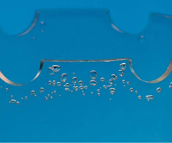
? 5. Bubbles
? Definition
When plastic melt is disturbed by gas during cavity filling, often appearing as silver streaks or tiny bubbles on the part surface, or bubbles formed inside thick sections. These gases mainly originate from moisture or volatiles in the material, excessive lubricant, or degradation gases from overheating/over-residence.
? Causes
- Excessive moisture content in material.
- Air entrapment in material.
- Polymer degradation.
- Material contamination.
- Barrel temperature too high.
- Poor melt plastification.
- Insufficient shot volume.
? Solutions
| Category | Solutions |
|---|---|
| Material | - Dry material according to supplier data before molding. - Improve material thermal stability. - Reduce powder additive usage to avoid air entrapment. - Use stable additives to avoid decomposition. |
| Mold Design | - Increase sprue, runner, and gate sizes. - Check for adequate venting. - Avoid sharp corners in gating system to prevent decomposition of heat-sensitive materials. |
| Molding Process | - Select appropriate machine; increase back pressure. - When switching materials, completely purge old material from barrel. - Avoid sucking in air during screw decompression; improve venting. - Reduce melt temperature, injection pressure, or injection speed. - When molding PVC/POM, purge barrel with ABS/AS etc., to avoid residual material decomposition and gas generation. |
? 6. Delamination (Peeling)
? Definition
Delamination refers to the part surface that can be peeled off layer by layer.
? Causes
- Incompatible polymer contamination.
- Excessive use of mold release.
- Melt temperature in cavity too low.
- Excessive moisture.
- Sharp corners in gates and runners.
- Inconsistent resin temperature.
? Solutions
| Category | Solutions |
|---|---|
| Material | - Avoid contamination by incompatible impurities or contaminated regrind. |
| Mold Design | - Apply radii to all sharp corners in runners or gates for smooth transitions. |
| Process Conditions | - Increase barrel and mold temperature. - Properly dry material before molding. - Avoid excessive use of mold release. |
? 7. Burn Marks
? Definition
Burn marks occur when melt is damaged by excessive temperature or prolonged residence, decomposing and releasing gas, forming obvious brown or silver streaks.
? Causes
- Trapped air in cavity not vented in time.
- Material degradation:
a. Excessive melt temperature.
b. Excessive screw speed.
c. Improper runner system design.
? Solutions
? Mold Design
- a. Add vents where venting is likely poor.
- b. Increase sprue, runner, and gate sizes.
? Process Conditions
- a. Reduce injection pressure.
- b. Reduce injection speed.
- c. Reduce screw speed.
- d. Reduce barrel temperature.
- e. Check if heaters, thermocouples are functioning normally.
? Inspection
-
- Check melt temperature by shooting "air shots" and using a needle pyrometer to measure actual temperature.
-
- Plastic degraded by heat may show no surface damage, but its mechanical properties are compromised.
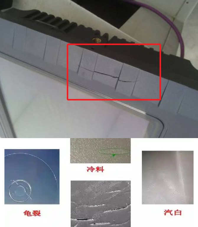
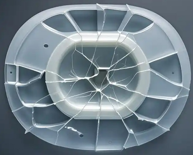
? 8. Cracking (Crazing)
? Definition
A common defect, including surface hairline cracks, micro-cracks, ejection stress whitening/cracking, and damage from part/mold sticking. Classified as ejection cracking and in-service cracking.
? Causes
Caused by stress deformation, mainly residual stress, external stress, and stress from environmental factors.
? Solutions
? Material Aspect
- Use mold release appropriately; regularly remove deposits like fumes from mold surface.
- Thoroughly dry material before processing.
- Use paints and thinners that won't cause cracking.
? Molding Process
- Avoid poor feeding during plastification introducing air.
- Increase melt and mold temperature; reduce injection pressure while ensuring flow.
- Reduce screw speed, injection speed; slow initial speed through gate; use multi-stage injection.
- Adjust mold opening speed and force to avoid cracking from fast, forceful ejection.
- Avoid weak areas from weld lines or material degradation leading to cracking.
- Anneal parts immediately after molding to relieve internal stress and reduce cracks.
- If surface crazing has occurred, consider annealing to eliminate it.
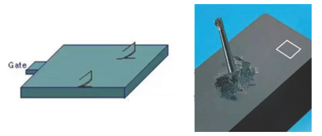
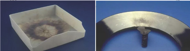
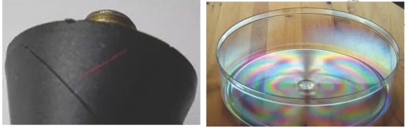
? 9. Residual Internal Stress
? Definition
Internal stress in plastics refers to stress generated during melt processing due to factors like molecular chain orientation and cooling shrinkage.
? Causes
- Cracking from internal stress or rainbow patterns at stress concentration points:
- Over-packing.
- Uneven wall thickness with gate in thin section.
- Too high packing density causing ejection difficulty.
- Direct gates with thin, shallow sections easily retain stress.
- Crystalline plastics cool too quickly, stress not easily released.
- Strain around inserts; prone to cracking and differential shrinkage from large temperature differences. To fully pack around inserts, high injection pressure is needed, creating excessive residual stress.
? Solutions
- Increase material and mold temperature within standard parameters.
- Shorten hold/pack time.
- For amorphous plastics, hold pressure need not be too high as they shrink less.
- Design uniform wall thickness; place gate in thick section.
- Eject uniformly.
- Pre-heat inserts (use tweezers/gloves for insertion).
- Avoid mixing virgin and regrind; e.g., PC prone to hydrolysis. If mixing, dry thoroughly.
- Increase sprue, runner, gate sizes to reduce flow resistance, aiding fill in distant areas.
- If residual stress exists, apply annealing.
- Increase nozzle orifice diameter; long nozzles need heater band control.
- Engineering plastics and glass-filled grades need mold temperature above 60°C.
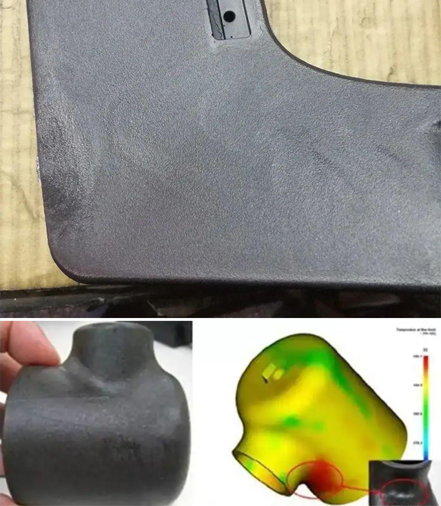
? 10. Glass Fiber Blooming (Fiber Readout)
? Definition
Glass fiber is used to enhance strength and heat resistance. However, compatibility issues arise between fiber and polymer. Fiber readout (or fiber prominence) is a direct manifestation of this.
? Causes
- Glass fiber flows much worse than polymer. Melt flows forward from the middle layer, with sides rolling outward. Best-flowing material goes to the front, while poorer-flowing (fiber) stays at the mold surface.
- Glass fiber promotes crystallization; PP and PA are crystalline. Fast crystallization leads to fast cooling; fast cooling makes it hard for resin to bind and conceal fibers, leading to readout.
? Solutions
? Material Aspect
- Consider compatibility; treat fiber surface with coupling agents or graft polymers.
- Add lubricants for fiber dispersion; some lubricants have external lubrication, migrating to surface to form a smooth layer.
- Other fillers.
? Processing Aspect
- Increase material and mold temperature.
- High pressure, high speed.
- Use Rapid Heat Cycle Molding (RHCM).
? Mold Aspect
- Make appearance surface matte or textured to reduce visual impact of fiber readout.
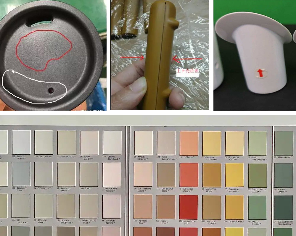
? 11. Color Variation
? Definition
Color differences on part surface due to temperature variations causing gloss differences. Unacceptable when clarity is critical. Influenced by resin, colorant (masterbatch/pigment), mixing, process, machine, mold, etc.
? Causes
- Greater difference in base color of resin leads to greater color variation.
- Colorant's base color, heat stability, dispersibility, hiding power.
- Compatibility between colorant and resin.
- Changing injection temperature directly affects melt temperature, altering color.
- Poor mold venting leads to adiabatic compression, intense reaction with oxygen.
- Nozzle size can affect color via shear rate influence.
- Storage time, impurities (moisture, fines), additives, other factors.
? Control Methods
| Category | Control Methods |
|---|---|
| Eliminate Machine & Mold Factors | - Select machine with appropriate shot capacity. - Repair mold parts (gating, vents) causing variation. |
| Eliminate Resin & Colorant Factors | - Strengthen incoming material inspection. - Use same supplier, same grade resin & masterbatch for same product. - Sample test colorants before mass production. - Focus on heat stability of resin and colorant. |
| Eliminate Poor Mixing of Colorant & Resin | - Manually stir material after loading hopper. - For products using dry color, use hot-air dryer and manual loading. |
| Reduce Barrel Temperature Influence | - Check/replace faulty heater bands or失控 temperature controllers causing drastic temperature swings. |
| Reduce Influence of Process Adjustments | - Avoid high injection speed, high back pressure causing strong shear. - Strictly control all barrel zone temperatures, especially nozzle and adjacent zones. |
| Understand Influence of Temp & Colorant Dosage | - Different colorants change color differently with temperature or dosage changes. Determine规律 via trial runs. |
? 12. Embrittlement
? Definition
Parts become brittle, prone to cracking or breaking in certain areas. Mainly caused by material degradation breaking polymer chains, reducing molecular weight and overall physical properties.
? Causes
- Improper drying conditions.
- Incorrect injection temperature settings.
- Poor gate and runner system design.
- Inappropriate screw design.
- Low weld line strength.
- Excessive use of regrind.
? Solutions
| Category | Solutions |
|---|---|
| Material | - Set proper drying conditions before molding. - Reduce regrind usage, increase virgin ratio. - Select higher-strength plastic. |
| Mold Design | - Increase sprue, runner, and gate sizes. |
| Injection Machine | - Select well-designed screw for more uniform plastification temperature. Uneven temperatures cause local overheating and degradation. |
| Process Conditions | - Reduce barrel and nozzle temperature. - Reduce back pressure, screw speed, injection speed to minimize shear heat and polymer breakdown. - If embrittlement is due to weak weld lines, increase melt temperature and injection pressure to improve weld line strength. |
? 13. Silver Streaks (Splay)
? Definition
Fine, elongated micro-cavities perpendicular to the principal stress direction under tensile stress. Includes surface bubbles and internal voids. Also called silver marks, mica marks, or bubbles. Appears as silvery streaks on part surface.
? Causes
- Excessive moisture in material.
- Air entrapment in material.
- Polymer degradation.
a) Material contamination.
b) Barrel temperature too high.
c) Insufficient shot volume.
? Solutions
| Specific Cause | Solutions |
|---|---|
| Melt surface temperature too high. | - Reduce barrel temperature. |
| Plastic residence time in barrel too long. | - Reduce total cycle time. - Shot size is too small for the molding requirement. |
| Melt temperature too low, causing unstable cavity fill time. | - Increase barrel temperature. - Increase nozzle temperature. - Increase mold fill speed. |
| Insufficient injection pressure. | - Increase injection pressure. |
| Temperature controller inaccurate, causing variations. | - Check controller for accuracy and control capability. |
| Mold surface temperature too low. | - Increase mold temperature. - Limit cooling flow rate through mold. |
| Unmelted cold slugs on part. | - Increase cold slug well size. - Enlarge runner ends to form additional cold slug wells. - Use electrically heated nozzles and sprue bushings. |
| Runners and gates too small or too long, causing freeze-off during delivery. | - Increase runner diameter and gate depth if needed. |
| Excessive mold release on mold surface. | - Thoroughly clean mold surface with white spirit. |
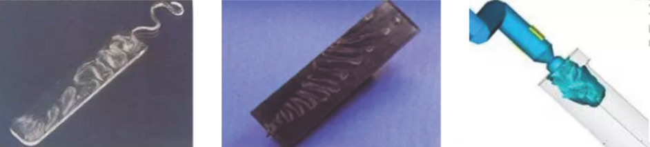
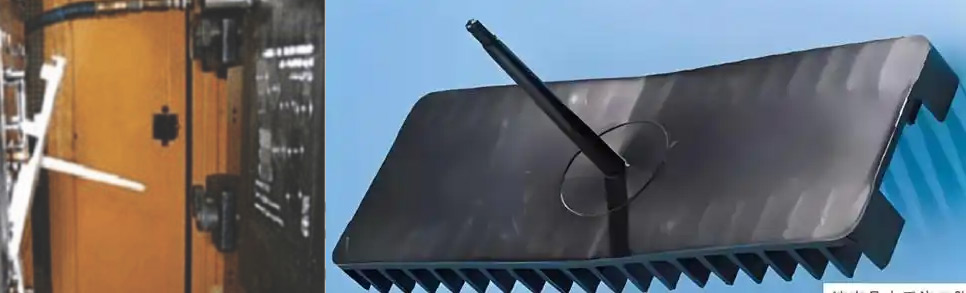
? 14. Jetting Marks
? Definition
When melt flows at high speed through narrow areas like nozzle, runner, or gate, then suddenly enters an open, relatively wide area. Melt snakes forward along flow direction, contacting mold surface and cooling rapidly. If this material doesn't fuse well with subsequent melt, jetting marks form on the part.
? Causes
| Category | Specific Causes |
|---|---|
| Primary Cause | Excessive injection speed starting from the gate. Improper fill rate; plastic shoots a long distance and cools rapidly before contacting cavity walls, forming jetting. |
| Mold Design | Poor gate location/type design; size too small; runner size too small; sudden increase in cross-section from gate to cavity causes unstable flow and jetting. |
| Molding Process | Injection speed too fast; injection pressure too high; melt/mold temperature too low. |
| Material | Brittle materials exacerbate jetting; large wall thickness variations cause flow instability when melt quickly moves from thin to thick areas, potentially causing jetting. |
? Solutions
| Category | Specific Measures |
|---|---|
| Mold Design | Add an obstacle (obstructor pin) in front of gate to prevent jetting. Increase gate cross-section. |
| Molding Process | Reduce injection speed is an option. Increase mold temperature to slow cooling rate of resin contacting cavity surface, helping prevent early surface skin formation. Reduce material flowability. Reduce melt temperature. |
| Material | Use material with lower flowability. |
? 15. Weld Lines
? Definition
Surface defects formed where two melt fronts meet and fuse. Also called knit lines or meld lines. Often the weakest point optically and mechanically. Notches or discoloration may appear along weld lines.
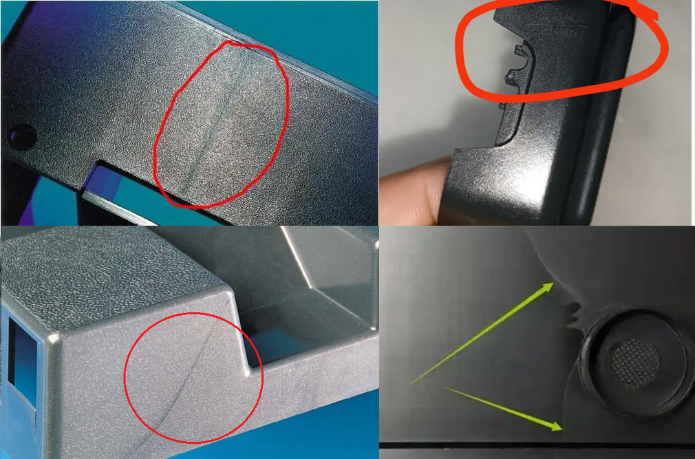
? Causes
- Insufficient temperature and pressure at the flow front meeting point causes filling difficulty at the edges of the fronts. On smooth surfaces, a notch along the weld line is visible; on textured surfaces, a gloss difference appears.
- The meeting point is not a single-phase fusion, creating a weak point.
- If plastics with additives (e.g., colorants) are used, additives align along the flow near weld lines, making color deviation more noticeable.
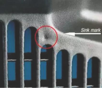
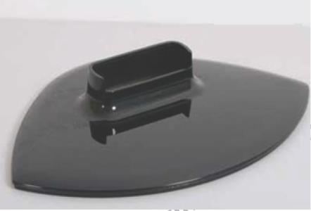
? 16. Sink Marks (Dents)
? Definition
Local surface depressions on parts, also called sinks, dents, shrinkage voids, sink marks, etc. Occurs in thick areas like ribs, counterbores, or internal grids. If shrinkage cannot be compensated, voids form.
? Causes
? Material Issues
- Excessive material shrinkage rate.
? Mold Issues
- Poor part design; excessive or uneven wall thickness.
- Gates too small or runners too narrow/shallow, causing early freeze-off.
- Non-uniform mold cooling.
? Molding Process
- Insufficient injection and inadequate packing.
- Injection speed too fast, injection/hold time too short, gate not frozen at end of hold.
- Melt temperature too high, prone to sinks in thick areas, ribs, etc.
? Solutions
| Category | Solutions |
|---|---|
| Material | - Dry material per supplier data before molding. - Switch to plastic with lower shrinkage. - Add nucleating agents to crystalline plastics to accelerate crystallization. |
| Mold Design | - Increase sprue, runner, gate sizes. - Check for adequate venting. - Use gas-assisted injection for ribs. |
| Molding Process | - Select appropriate machine and mold. - Completely purge old material from barrel when switching. - Increase injection speed to fill and eliminate most shrinkage. - Improve venting system. - Reduce melt temperature, increase injection pressure or speed. - Increase back pressure; leave cushion at screw tip after injection for packing. |
| Part Design | - Avoid large thickness variations causing differential shrinkage and sinks; if variation is necessary, use gradual transitions. |
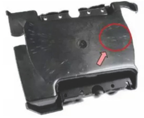
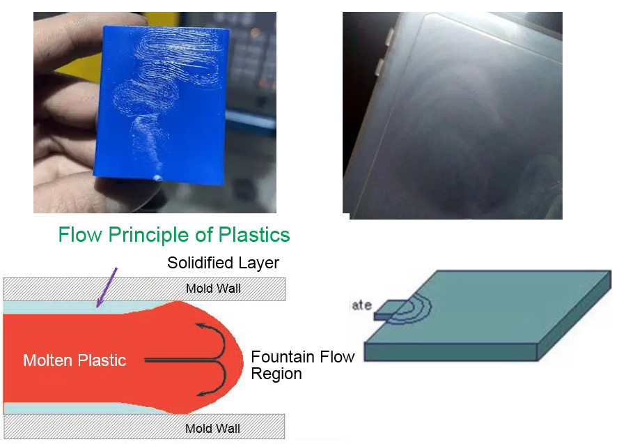
? 17. Flow Marks
? Definition
Wavy surface defects near the gate. Appears as concentric circle patterns on the part surface, centered on the gate direction, imprinting the resin flow path.
? Causes
- Melt temperature too low.
- Mold temperature too low.
- Injection speed too low.
- Injection pressure too low.
- Runner and gate sizes too small.
? Solutions
| Category | Specific Measures |
|---|---|
| Material | Increase material flowability. Reduce rubber content or toughening agents, or reduce their particle size. |
| Mold Design | Increase cold slug well size in runner to trap cold slugs. Improve mold venting. Increase runner and gate sizes. Shorten sprue length or switch to hot runner system. |
| Molding Process | Increase injection speed. Increase injection and hold pressure. Extend hold time. Increase mold temperature. Increase barrel and nozzle temperature. |
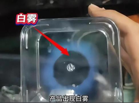
? 18. Haze (Cloudiness)
? Definition
A white haze on the product surface. Visually appears white, so less noticeable on white parts, most obvious on black high-gloss parts. On PR material parts, white cloud-like patterns of varying sizes appear around the surface, classified as white haze.
? Causes
During the transition from glassy to rubbery to molten state, gaps between plastics are compressed, generating gas inside the melt. If gas isn't vented from the barrel during plastification, it's carried into the cavity. Whether the mold can vent it depends on mold venting, leading to haze (trapped gas) or burning.
? Solutions
? Mold
Venting isn't solved solely by the mold. For PP, with its wide processing window and excellent flow, vents that are too large or misplaced won't vent properly and can cause flash. Correct venting is key.
? Process
- Reducing screw speed gives more uniform melt temperature and less air entrapment. High screw speed increases air entrapment; high shear generates uneven heat, causing decomposition and gas.
- Increasing mold temperature allows for high-pressure, slow filling. Low mold temperature causes early surface freeze-off, preventing slow fill and possibly short shots.
- Reducing injection speed: faster speed compresses gas quickly, raising temperature. Slower speed allows gas to escape.
- Clamp force: Higher clamp force reduces venting effectiveness at the parting line; lower force improves it.
? 19. Ejection Deformation
? Definition
Poor ejection, also known as sticking in sprue, occurs due to poor contact between sprue bushing and nozzle radius, sprue not ejecting with part, or abnormal packing. Usually, sprue diameter should be large enough so that sprue isn't fully frozen during part ejection.
? Causes
- Mold malfunction.
- Improper process control.
- Material not suitable.
- Improper mold release use.
- Over-packing.
- Part sticks to stationary mold half.
? Solutions
| Defect Analysis | Corrective Actions |
|---|---|
| Over-packing in mold. | Reduce injection pressure; reduce shot size; adjust if barrel temperature is too high. |
| Injection pressure maintained too long. | Reduce screw forward (hold) time. |
| Mold surface scratched, porous, or abraded. | Remove defects and polish mold surface. |
| Insufficient draft angle on mold. | Use minimum draft angle of 0.5° per side. |
| Poor undercut design. | Ensure undercuts have no sharp corners. |
| Part sticks to highly polished mold surface. | Use vent pins to break vacuum when ejecting from highly polished surfaces. |
| Inadequate ejection system. | Increase number of ejector pins or change system type. |
| Insufficient plastic lubrication. | Use mold release if allowed; add external lubricant like zinc stearate. |
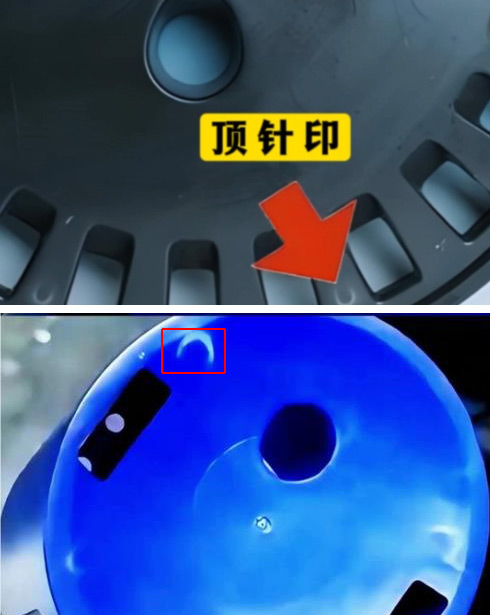
? 20. Ejector Pin Marks
? Definition
Generally refers to stress whitening or protrusions seen on part appearance at ejector locations, or暗痕/shadows on the opposite side of the pin (no protrusion or depression, just a gloss difference).
? Causes
- Unreasonable product design (part geometry).
- Unreasonable mold design (gating, gate design, ejector design, cooling, venting).
- Unreasonable machine parameters (injection, hold, mold temp, material temp, ejection, clamp force).
- Unreasonable material influence (processing parameters).
? Specific Problems and Solutions
| Specific Problem | Solutions |
|---|---|
| Product Design | For simple parts, wall thickness should be at least 2.5mm; for complex parts with many ribs, at least 2.8mm. |
| Ejector pin marks from pin deformation under molding pressure. | Reduce molding pressure (by modifying runner/gate size) or modify pin size; change pin to blade ejector. |
| Ejector pin marks from pin deformation under ejection force. | Consider if pin location is at point of maximum force and if ejection is balanced. |
| Ejector pin marks from different thermal conductivity of pin vs. mold steel. | Add 0.05–0.20mm material at pin location; apply texture or grain to pin surface. |
| Ejector pin marks influenced by cooling channels. | Low mold temp容易产生 stress;适当提高 temp reduces stress; increase injection speed appropriately; adjust cooling layout. |
| Optimal machine and parameter selection. | Machine selection; molding conditions; processing temperature; injection pressure/speed/time; hold pressure/time; cooling time. |
? 21. Wrinkles (Orange Peel)
? Definition
Flow marks frequently appearing around the gate area or surface wrinkles at the end of flow.
? Causes and Solutions
| Cause | Solutions |
|---|---|
| Injection Machine | |
| Melt temperature too low. | Increase temperature in first two barrel zones. |
| Mold fill speed too slow. | Increase injection speed; increase injection pressure. |
| Mold temperature too low. | Increase mold temperature. |
| Mold | |
| Runner and gate too small. | Increase runner diameter and gate width if needed. |
| Plastic | |
| Plastic viscosity too high. | Select a more free-flowing grade. |
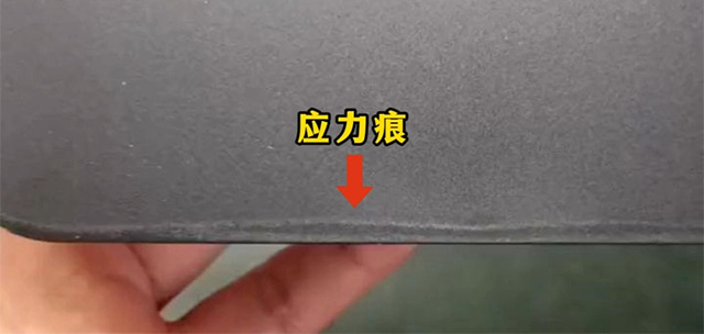
? 22. Stress Marks
? Definition
Mostly appear on part edges near the parting line. A collection of countless stretch-oriented molecules perpendicular to flow direction, with fine gaps between them. Polymer chains still connect along the stress mark direction, so it's not a crack. Appropriate heating may allow stretched molecules to relax, making marks disappear.
? Causes
Uneven wall thickness causes stress marks from uneven flow and cooling shrinkage; stress marks at ejector pins are from rapid local mold temperature rise during molding.
? Solutions
? Product Design
- Overall wall too thin or thick flow ends require high pack pressure; add material or thin out thick ends. If reducing pack pressure, check if thinning sink areas helps; if not, increase overall thickness.
- Avoid wall thickness variations; if necessary, use large radii.
- Avoid large ribs on core side causing stress marks on cavity side.
? Mold Design
- Gates too small or too few, unevenly distributed.
- Moving parts fit too loosely or poor cooling layout causing high local mold temp.
? Process Conditions
- Set appropriate hold pressure and time (reduce).
- Increase or decrease mold temp (increase improves fill, reduces pack pressure; decrease makes texture glossier, blending with stress marks; usually decreasing is chosen).
- Increasing speed helps reduce residual orientation stress (slightly helps thin-wall warpage, little effect on stress marks).
- Increasing melt temp, back pressure, screw speed has minimal effect on stress marks.
? 23. Color Instability
? Definition
In production, color may change every few days, or even several times a day.
? Causes
- Poor color mixing in machine barrel.
- Colorant not uniformly coating pellets; pigment particles too coarse.
- Low concentration of masterbatch; inconsistent liquid colorant dosing.
- Variations in plastic feed; "fines" and dust when mixing virgin and regrind.
? Solutions
| Cause | Solutions |
|---|---|
| Poor color mixing in barrel. | Increase back pressure. Reduce barrel temperature for better plastic mixing. |
| Colorant not uniformly coating pellets. | Pre-mix pigment with plastic using a wetting agent before molding. |
| Pigment particles too coarse. | Grind dye to fine powder. |
| Masterbatch concentration too low. | Use dry color, masterbatch, or liquid colorant with correct concentration. |
| Inconsistent liquid colorant dosing. | Check for air block in feed line and screw slippage. |
| Variations in plastic feed. | When coloring virgin/regrind mix, remove all "fines and dust." |
? 24. Hesitation (Flow Hesitation)
? Definition
When melt enters the cavity from the gate, flow slows or stops in some directions—this is hesitation. It is an extreme form of unbalanced flow, causing many defects.
? Causes
In practice, cavities have thick/thin areas, straight/curved surfaces, cool/hot spots, creating different pressure and temperature gradients. Where flow slows, the skin quickly freezes due to heat loss, the flowing core thins further, slowing more—hesitation forms.
? Improvement Methods
- Changing mold structure is the most fundamental way. Improve design for rational part geometry, avoid sudden wall changes, making flow resistance roughly uniform.
- Changing parameters can alleviate hesitation: increase melt temperature, increase injection speed, but distinguish between temperature-sensitive and shear-sensitive materials.
- Changing mold temperature has little effect.
- Changing material is not ideal and has limited effect.
? 25. Gloss Differences (Matt & Glossy Surfaces)
? Definition
Severe stress in molded parts causes gloss differences, uneven texture appearance (dull and shiny areas), or inconsistent gloss on high-gloss parts, greatly reducing appearance.
? Causes
When plastic cools from melt to solid, it continuously shrinks with temperature change. Temperature and shrinkage affect replication. High-shrinkage plastics tend to look dull; low melt/mold temperature causes dullness immediately upon contact. Low injection/hold pressure results in low packing density, also causing dullness.
? Solutions
| Specific Cause | Solutions |
|---|---|
| Gloss differences around parting line. | Ensure adequate venting, especially at flow ends. |
| Areas near gate shiny, far from gate dull. | Maximize gate size without causing excessive shear and local gloss differences. Use low pressure, low speed, low melt temperature where possible. Use mold vents to alter flow speed. |
| Areas with uneven wall thickness and large flow speed variations. | Restrict flow in thicker areas to deliberately change flow direction/speed. Add vents in thinner areas. |
| Gloss differences at corners. | Make corner thickness uniform with side walls to reduce effect. |
| Gloss differences opposite ribs on back side. | Minimize ribs on back of appearance surface (especially tall ribs). Reduce rib thickness. |
| Gloss differences near weld lines. | Strengthen venting at flow ends. Avoid aligned weld lines; scatter them via flow restriction and venting. |
| Non-uniform cooling channel layout causing hot/cold spots and gloss differences. | Make cooling as uniform as possible within structural constraints. |
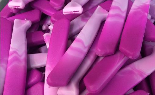
? 26. Color Mixing (Streaking)
? Definition
Color streaking is related to the screw, mainly when other material isn't purged cleanly. Most importantly, added material has mixed colors, or barrel isn't clean.
? Causes/Solutions
- Improper shot size vs. plasticating capacity; poor screw mixing.
- Material itself mixed; barrel not cleaned,残留 other material.
- Screw speed too fast, poor mixing; poor pigment/masterbatch dispersion.
? Solutions
? Generally, for color streaking:
- Increase back pressure appropriately.
- Or raise melt temperature 10–15°C.
- Or add some dispersing oil for coloring.
- Increase regrind usage.
- Improve mixing operation.
- If screw speed too fast, reduce by 20–50 RPM.
? For severe streaking:
- Set screw speed to 100–150 RPM, then increase back pressure until plasticating time approaches part cooling time. This greatly increases heating time and mixing次数 without affecting cycle time, significantly improving melt quality and reducing streaking. If needed, extend plasticating time further.
- Increased shear time/speed raises melt temperature, possibly changing color; adjust color if needed.
- Pre-mix material and pigment, then compound/pelletize. Pelletized material几乎 eliminates streaking, but monitor color change.
- If above methods fail, move mold to a larger, better, or newer machine. Small or old machines are key reasons streaking is hard to solve.
? 27. Wall Thickness Design Guidelines
? Wall Thickness Selection
Injection molded parts require sufficient thickness for strength and mechanical properties. However, considering lightweight, material saving, and cost, minimize thickness to shorten cycle time, reduce weight, and optimize material use.
? Selection Basis
? Both excessively thin and thick walls are不合理.
Thermoplastic parts often have wall thicknesses of 1–4 mm; minimum generally not less than 0.6–0.9 mm. Large parts can be 6 mm or thicker. Thermoset parts: small parts 0.7–2.5 mm; large parts 3–8 mm.
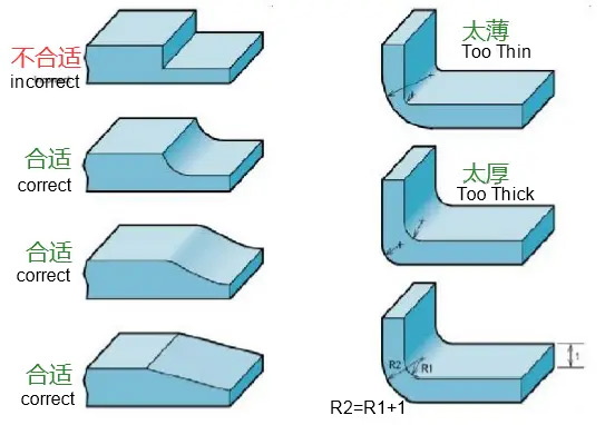
? Walls should be as uniform as possible.
- While meeting functional needs, minimize thickness and keep it uniform for optimal mold filling and predictable shrinkage, reducing internal stress.
- Use radii or tapered transitions for thickness changes.
- To avoid or reduce weld lines, keep wall thickness consistent within a part.